Introduction
Setting up a Clausing 8540 horizontal mill is manageable for a trained machinist or rigging-aware shop team — but it demands careful planning. Four factors drive that complexity:
- ~1,000 lb machine weight requiring proper rigging equipment
- Top-heavy center of gravity concentrated over a narrow 20-inch base
- 3-phase electrical requirements needing site verification before delivery
- Precision alignment needs once the machine is in final position
This guide covers key specifications, site preparation requirements, step-by-step setup from delivery to first cut, and how to avoid the most common installation mistakes. Whether you're commissioning a newly acquired machine or relocating an existing unit, this guide gives you a clear path from crate to cutting.
TL;DR
- At ~1,000 lbs with a rear-biased center of gravity, always move this machine with a shop crane, forklift, or professional riggers
- Single-phase shops need a VFD rated for at least 3 hp — the motor is 1.5 hp 3-phase (derate using motor FLA × 1.73)
- Spindle is a hardened 30 ASA taper with 12 speeds (52–2,000 rpm); takes 7/8", 1", and 1-1/4" arbors
- Table is 26.125" × 6.76" with 17.25" longitudinal, 5" traverse, and 14" vertical travel (power feed models: 15.375" longitudinal)
- Before commissioning, verify spindle run-out (≤0.0005" TIR), table movement, and hydraulic speed-change function
Clausing 8540 Specifications: What This Machine Is Built For
The Clausing 8540 is a production-grade horizontal knee mill built for slab milling, side milling, gear cutting, and slotting in job shops and industrial environments. It belongs to the 8500 Series, which includes models 8541, 8550, 8551, and the rare 8513.
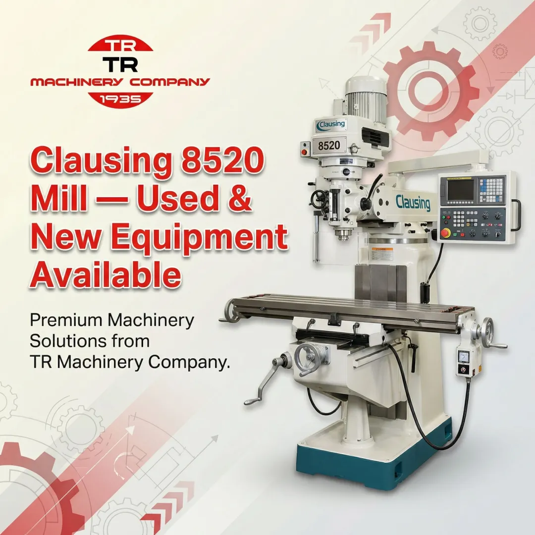
T.R. Wigglesworth Machinery Co., an authorized Clausing dealer for over 40 years, carries used Clausing horizontal mills and replacement parts for buyers sourcing machines or components.
Spindle and Drive System
The spindle is constructed from alloy steel and features:
- Taper: Hardened 30 ASA (International) taper nose conforming to ANSI B5.18-1972 (R2014)
- Bearings: 3.5" diameter Timken taper roller bearings (lubricated-for-life)
- Bore & Drawbar: 21/32" bore with 21/32" × 13 tpi drawbar thread
- Run-out: Clausing's guaranteed run-out is better than 0.0005" TIR
Speed System:
The 8540 uses an infinitely variable expanding/contracting pulley drive with a hydraulic rotary speed selector, offering 12 selectable speeds:
- Backgear range: 52 to 280 rpm
- Direct drive range: 360 to 2,000 rpm
The backgear assembly runs in an oil bath and multiplies torque by approximately 6×, ideal for heavy cuts in tough materials. A 3 V-belt final drive transmits power to the spindle.
Arbor Compatibility:
Available arbor diameters are 7/8", 1", and 1-1/4". Verify arbor diameter when sourcing cutters or adapters.
Table, Work Envelope, and Feed System
Table Dimensions:
- Size: Ground-finished 26.125" × 6.76" surface
- T-slots: 3 slots for 1/2" bolts
- Travel: 17.25" longitudinal (reduces to 15.375" when power feed is fitted), 5" traverse, 14" vertical
Feed System:
The 8540 features a dual feed system:
- Hand-operated fast feed — permanently attached handle on a reduction gearbox (1:1 push-in, 4:1 pull-out ratio for rapid repositioning)
- Power feed — 12 rates from 0.44 to 9.54 ipm, delivered via a column-mounted gearbox, universally jointed shaft, and knee-mounted reversing gearbox with automatic knock-off and overload clutch
Model Variants: Choosing the Right Configuration
Understanding model naming helps confirm your machine's configuration:
| Model | Motor Phase | Feed Type | Longitudinal Travel |
|---|---|---|---|
| 8540 | 3-phase | Power feed | 15.375" |
| 8541 | Single-phase | Power feed | 15.375" |
| 8550 | 3-phase | Hand feed | 17.25" |
| 8551 | Single-phase | Hand feed | 17.25" |
| 8513 | Varies | Factory special | Features Bridgeport M head |

Overall footprint: Approximately 59" wide × 46" deep × 56" tall.
Before You Begin: Prerequisites and Safety for Setup
Site Readiness
Floor Space:
Confirm at least 59" × 46" clear floor space with adequate clearance on all sides for operator access, full table travel, and overarm removal.
The floor must be level and capable of bearing concentrated loads. For machines in the 1,000 lb class, ensure the concrete slab is free of underlying voids and capable of supporting concentrated point loads without settling.
Electrical Prerequisites
The 8540 requires a 3-phase supply for its 1.5 hp motor. Shops with single-phase power must install a VFD or rotary phase converter first.
VFD Sizing Rule:
Because a VFD's rectifier must charge DC bus capacitors using only two legs instead of three, multiply the motor's full-load amperage by 1.73 to determine the required single-phase input rating. For a 1.5 hp motor, plan on a VFD rated for at least 3 hp.
Confirm voltage and amperage ratings of the existing circuit match motor nameplate data. NEC Article 430.122 requires that circuit conductors supplying the VFD carry an ampacity not less than 125% of the VFD's rated input current.
Critical Non-Negotiables
- Do NOT attempt to move or reposition the machine without proper lifting equipment rated for at least 1,000 lbs
- Never stand within the tipping radius during a lift — the center of gravity sits near the rear of the 20" base footprint, making it top-heavy and prone to tipping
- Never lift from the base — this creates severe tipping risks
Required Tools and Materials
- Shop crane or forklift (minimum 1-ton capacity)
- Soft lifting sling rated for the load
- Ratcheting cargo straps
- Precision machinist's level
- Pry bar or jack for fine positioning
- Appropriate T-slot hardware
- Correct arbor and drawbar for intended cutters
- Cutting fluid supply
How to Set Up the Clausing 8540 (Step-by-Step)
Setup runs in a fixed sequence: moving, placing, leveling, connecting power, and commissioning. Skipping steps — especially leveling and electrical validation — causes alignment drift, premature bearing wear, and failed cuts.
Moving and Positioning the Machine
Two rigging approaches work for this machine:
- Primary method: Attach a soft sling under the overarm bars, clinched securely around the rear spindle pulley area to prevent forward slide. Sliding forward drops the machine diagonally and can overload or tip the crane.
- Alternative: Slide overarms rearward past the column casting and lock them, then sling fore and aft of the column to lift directly over the center of gravity.
Keep sling angles as vertical as possible. Per ASME B30.9, dropping from 90° (vertical) to 30° from horizontal doubles the tension on each sling leg.
Once on the shop floor, use a platform truck or bar-and-roller method for fine positioning. Lower using crane hydraulics — open the release valve slowly to avoid sudden drops. Do not anchor permanently until leveling is confirmed.
Leveling, Anchoring, and Electrical Hookup
Leveling Procedure:
- Place a precision machinist's level on the table surface (both longitudinal and traverse axes)
- Adjust by shimming the base until within acceptable tolerance
- Confirm the knee moves freely across the full 14" vertical travel without binding after leveling
Electrical Hookup:
Connect the motor to the 3-phase supply or VFD per the motor nameplate wiring diagram. Verify correct rotation direction before installing the arbor — incorrect rotation will pull the drawbar loose and eject tooling.
Test the hydraulic speed-change mechanism through all 12 speed positions under no load first. Turn the variable dial back to low speed, stop, and hold there for 30 seconds to permit the hydraulic bypass valve to open.
Arbor Installation and Initial Commissioning
With leveling confirmed and power validated, arbor installation is the final mechanical step before the first test run.
Arbor Installation:
- Select the correct arbor diameter (7/8", 1", or 1-1/4") for the planned cutters
- Thread the drawbar through the spindle bore
- Tighten to spec and verify there is no lateral play
- Confirm overarm support bracket is snug against the arbor support bearing
Initial Commissioning Run:
- Start at mid-range speed in direct drive (no backgear)
- Observe for unusual noise or vibration at each speed step
- Verify table feeds engage and disengage cleanly
- Check that the auto knock-off on the power feed operates correctly
- Measure spindle run-out with a dial indicator — target is better than 0.0005" per Clausing's specification

Common Setup Problems and How to Fix Them
Spindle Run-Out Exceeds Specification
Problem: Dial indicator shows run-out greater than 0.0005" TIR after setup.
Likely Cause:
- Drawbar insufficiently tightened
- Debris in the spindle taper
- Bearing damage from a previous tip or impact — check for true brinelling (indentations in the raceway with original surface grinding marks still visible) or false brinelling (wear grooves from transport vibration). See Timken's bearing damage reference guide for identification.
Fix:
Clean and re-seat the arbor taper, re-torque the drawbar, and recheck. If run-out persists, inspect Timken bearings for wear or brinelling and replace as needed.
Hydraulic Speed-Change Mechanism Is Unresponsive or Sluggish
Problem: Rotating the speed selector produces no change or delayed response in spindle speed.
Likely Cause:
Hydraulic fluid in the speed-change system is low, contaminated, or has air in the line — common after transport or a tip-over event.
Fix:
- Locate the hydraulic line connecting the speed-change knob to the actuator on the motor's expanding/contracting pulley.
- Check fluid level and condition — discard fluid that appears milky or contaminated.
- Bleed air from the system.
- Refill with the correct fluid grade specified in the service manual.

Power Feed Fails to Engage or Trips Immediately
Problem: Power feed clutch does not engage, or engages briefly then trips the overload.
Likely Cause:
- Overload clutch is set too sensitively
- Drive shaft universal joint is misaligned after repositioning
- Reversing gearbox at the knee is not fully seated
Fix:
Check shaft alignment between the column-mounted feed gearbox and the knee reversing gearbox. Re-seat any couplings. Adjust overload clutch sensitivity via the Spring Adjusting Nut, accessed through a threaded hole in the lower left side of the carriage — see the Practical Machinist thread on Clausing power feed adjustment for reference. Do not bypass the overload clutch — it protects the table screws.
Pro Tips for a Successful Clausing 8540 Setup
Rigging and Timing
Never move this machine while fatigued or short-staffed — its top-heavy geometry punishes inattention. Plan the move with at least two people, proper slings, and a crane or forklift staged before work begins. T.R. Wigglesworth Machinery Co. offers delivery and installation support if professional rigging is needed.
Get the Manual First
Before powering up, obtain the Operation, Maintenance, and Parts Manual for your specific variant (8540 vs. 8541, etc.). Manuals are available through specialist machine tool archives, dealers like T.R. Wigglesworth, and the Clausing Service Center — covering wiring diagrams, lubrication schedules, and torque specs required for safe commissioning.
Validate Before Production
Run the machine through its full speed and feed range using a test cut on sacrificial material before committing it to production. Note any anomalies in noise, vibration, or feed consistency — and resolve them before the machine touches actual parts.
Frequently Asked Questions
What is a Clausing 8540 horizontal mill used for?
The 8540 is used for slab milling, side milling, slotting, straddle milling, and gear cutting. These operations benefit from the horizontal spindle's torque and rigidity, making it ideal for heavy stock removal in job shop and industrial production environments.
What materials can be milled on a Clausing 8540 horizontal mill?
It can machine steel, cast iron, aluminum, brass, bronze, and other common engineering materials. The backgear system's approximately 6× torque multiplication makes it particularly capable on harder or tougher materials that require slow speeds and high torque.
What is the difference between a Clausing 8540 horizontal mill and a universal mill?
A universal mill adds a swiveling table (allowing helical milling), whereas the 8540 is a plain horizontal mill with a fixed table. The 8540 is better suited for straightforward production milling, while universal mills offer greater flexibility for complex geometries.
How does the Clausing 8540 differ from a vertical mill?
The 8540 uses a horizontal spindle and arbor-mounted cutters for wide, powerful cuts across a workpiece surface, while vertical mills use a vertical spindle better suited for drilling, contouring, and face milling. Horizontal mills generally offer higher torque and better chip evacuation for heavy slab work.
What motor and power supply does the Clausing 8540 require?
The 8540 uses a 1.5 hp 3-phase motor. Shops without 3-phase service can run it via a variable frequency drive (VFD) converting single-phase input, which also enables variable speed control independent of the pulley mechanism.
What spindle arbor sizes does the Clausing 8540 accept?
The 8540 accepts three arbor diameters: 7/8", 1", and 1-1/4". The spindle uses a 30 ASA taper and a 21/32" × 13 tpi drawbar, so tooling must match these specifications for a secure, concentric hold.