
Introduction
Precision surface grinding uses a rotating abrasive wheel to remove controlled amounts of material from a workpiece, producing flat surfaces with tight dimensional tolerances and fine surface finishes. It's the finishing process engineers and machinists in aerospace, medical device manufacturing, mold machining, and heavy industry rely on for final-stage accuracy.
Inconsistent flatness, thermal damage, chatter, and poor surface finish can result from several interacting factors, including wheel specification and condition, dressing practice, infeed and table-speed settings, coolant delivery, workholding, machine condition, and measurement methods. Diagnosing the result requires evaluating the complete grinding system rather than changing one parameter in isolation.
This guide walks through how the precision surface grinding process works, what factors influence its outcomes, where it fits in a production workflow, and when it may not be the right choice.
Key Takeaways
- Precision finishing: Conventional reciprocating surface grinding is commonly used to control thickness, flatness, parallelism, and surface finish; achievable results depend on the machine, workpiece, wheel, setup, environment, and measurement method
- Multiple machine configurations: Surface grinders may use reciprocating or rotary tables, horizontal or vertical spindles, and magnetic, vacuum, or mechanical workholding
- Process position: Grinding is often performed after milling or heat treatment, but its place in the routing depends on stock allowance, material condition, and final drawing requirements
- System-dependent results: Wheel specification and condition, dressing, infeed, table speed, coolant, workholding, machine condition, and inspection all influence the outcome
- Application fit: Conventional precision surface grinding is not automatically the best choice for every stock-removal rate, part geometry, material, or tolerance requirement
What Is Precision Surface Grinding?
Precision surface grinding is a machining operation that uses an abrasive wheel with many geometrically undefined cutting edges to remove controlled amounts of material from a workpiece surface. Its objectives commonly include final thickness, flatness, parallelism, and a specified surface-texture parameter such as Ra or Rq; these parameters are defined and measured differently and should not be used interchangeably.
How It Differs from Milling and Turning
Milling and turning use tools with a defined number and geometry of cutting edges, while a grinding wheel contains many abrasive grains that interact with the workpiece through cutting, plowing, and rubbing. Surface grinding can achieve demanding dimensional and finish requirements, but the result must be established for the specific machine, material, wheel, workholding, process, and inspection method rather than assumed from the process name alone.
Blanchard vs. Precision Surface Grinding
These two processes are often confused, but they serve different purposes:
| Blanchard Grinding | Precision Surface Grinding | |
|---|---|---|
| Spindle orientation | Vertical spindle, rotary table | Horizontal spindle, reciprocating passes |
| Primary purpose | Rapid bulk stock removal | Tight tolerances, fine finishes |
| Typical flatness | ±0.001" | ±0.0001" |
| Surface finish | Cross-hatch scratch pattern | 8 Ra or better |
| Best for | Large, rough workpieces | Accuracy-critical components |
How the Precision Surface Grinding Process Works
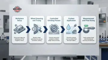
The precision surface grinding process follows a controlled sequence:
- Follow the machine and wheel manufacturers’ operating procedures and verify that required guarding is in place
- Inspect the wheel before mounting, use the required mounting components, and confirm that machine spindle speed does not exceed the wheel’s marked maximum operating speed
- Clean and secure the workpiece using a workholding method appropriate for its material, geometry, thickness, and cutting forces
- Dress and true the wheel using a method compatible with its abrasive, bond, and required wheel form
- Establish conservative infeed, crossfeed, table-speed, wheel-speed, and coolant settings for the specific application
- Grind and measure the workpiece according to the approved process until the specified dimension, form, and surface-texture requirements are met
Core cutting action:
Abrasive grains at the wheel surface interact with the workpiece through cutting, plowing, and rubbing. Wheel speed must remain within the ratings and operating limits specified by the wheel and machine manufacturers; the correct value depends on wheel construction, diameter, abrasive, bond, machine, material, and operation.
Excessive grinding heat can cause burn, dimensional change, residual-stress alteration, tempering, or metallurgical transformation in susceptible materials. The resulting surface integrity depends on the alloy, initial heat treatment, temperature-time history, heating and cooling rates, wheel condition, material-removal rate, and coolant system, so one temperature cannot be used as a universal damage threshold.
Process control and measurement:
Operators or CNC controls may manage:
- Infeed or depth of cut
- Crossfeed and table speed
- Wheel speed within the approved operating range
- Dressing method, amount, and frequency
- Coolant flow, concentration, filtration, temperature, and nozzle position
- Spark-out or dwell strategy, where applicable
Inspection must match the drawing requirement. Micrometers, height gauges, indicators, surface plates, optical flats, or CMMs may be used for dimensions and geometric form, while specified surface-texture parameters such as Ra or Rq require an appropriate contact or non-contact surface-measurement instrument and a defined measurement procedure.
Equipment types:
Horizontal-spindle reciprocating-table machines are commonly used for precision flat work. Rotary-table machines are available in horizontal- and vertical-spindle configurations, and their appropriate use depends on workpiece size, stock-removal requirements, finish, accuracy, and production volume.
T.R. Wigglesworth lists new and used grinding equipment and surface-grinder categories associated with brands including KENT, CLAUSING, ACER, and SUPERTEC. Current models, configurations, availability, and performance specifications should be confirmed for the individual machinery project.
Step 1: Workpiece Preparation and Setup
Before grinding begins, the workpiece and chuck or fixture should be clean and free of burrs, chips, and raised damage that could prevent stable seating. The operator confirms the starting dimensions, stock allowance, support condition, and required datum before securing the part.
Ferromagnetic workpieces are often held on permanent-magnetic or electromagnetic chucks. Safe holding capacity must be determined from the chuck manufacturer’s data and the workpiece’s material, thickness, contact area, pole coverage, flatness, and surface condition; nonmagnetic or unsuitable workpieces may require vacuum, mechanical, adhesive, or purpose-designed fixturing.
Step 2: Wheel Dressing and Truing
The grinding wheel must be dressed (sharpened) and trued (made concentric) before use and periodically during the job. A dull or loaded wheel generates excess heat, causes chatter, and degrades surface finish. Passing a diamond dresser across the wheel face exposes fresh abrasive grains and restores geometry. Decreasing the dressing lead (slower traverse speed) creates a "closed" wheel face that improves surface finish but increases grinding forces and thermal risk; increasing the lead creates an "open" wheel face, improving cutting ability and reducing heat at the cost of a rougher finish.
Step 3: Grinding Passes and Final Sizing
Grinding parameters should be established from the machine and wheel manufacturers’ recommendations and validated for the workpiece material, hardness, contact area, wheel specification, coolant system, and required result. Roughing commonly prioritizes controlled stock removal, while finishing uses settings selected to limit heat and meet the final dimensional and surface-texture requirements.
Spark-out passes, made without additional programmed infeed, may reduce the effect of residual system deflection and allow the wheel to remove remaining high points. Spark-out does not guarantee accuracy; the workpiece must still be inspected using the methods and environmental controls required by the drawing.
Where Precision Surface Grinding Is Typically Applied
Precision surface grinding is most commonly performed as a late-stage or final operation — after sawing, laser/plasma cutting, milling, turning, or heat treatment. Heat treatment in particular causes distortion in tool steel and hardened components, making post-treatment grinding the standard method for correcting warping and bringing parts to final specification.
Industries and components:
- Hardened die blocks, mold plates, parallels, fixture plates, and tooling components requiring controlled flatness or thickness
- Flat aerospace and defense components where surface grinding is specified and the machine, wheel, material, and process have been qualified
- Flat medical-instrument or device components produced under the manufacturer’s validated quality and biocompatibility requirements
- Gauge, inspection, and reference components requiring controlled flat and parallel surfaces
- Machine-tool ways, slide components, wear plates, and mating surfaces
- Production parts requiring a specified flat surface, thickness, parallelism, or surface texture
Complex forms such as turbine-blade root profiles generally require a profile-capable grinding process and dedicated tooling rather than conventional flat surface grinding. Production scale depends on machine automation, loading, dressing, inspection, cycle time, and process stability.
Key Factors That Affect Precision Surface Grinding Outcomes
Grinding Wheel Specification
Wheel selection—abrasive type, grit size, bond type, and hardness grade—is one of the most critical decisions. An incorrect wheel choice for the material being ground leads to poor finish, rapid wear, or workpiece damage.
Abrasive selection by material:
| Workpiece Material | Recommended Abrasive | Why |
|---|---|---|
| Soft/Low-Alloy Steels | Aluminum Oxide (Al₂O₃) | Standard for ferrous metals; balances sharpness and toughness |
| Cast Iron / Non-Ferrous | Silicon Carbide (SiC) | Friable grain fractures to stay sharp on softer materials |
| Hardened Tool Steels (>50 Rc) / Superalloys | Cubic Boron Nitride (cBN) | Extreme hardness and thermal stability prevent rapid wear and burn |
| Carbides / Ceramics / Glass | Diamond | Hardest abrasive; only option for non-ferrous ultra-hard materials |
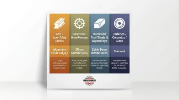
Using alumina on hardened alloys or superalloys causes the grains to dull rapidly, generating excess friction and inducing thermal burn. Highly heat-sensitive materials require friable seeded-gel alumina or cBN to ensure grains self-sharpen.
Grit size and surface finish:
| Grit Size (Mesh) | Expected Finish Ra (µin) |
|---|---|
| 46 | 32–42 |
| 80 | 21–26 |
| 120 | 14–16 |
| 220 | 2–3 |
Finer grit sizes produce smoother finishes but lower the permissible material removal rate.
Depth of Cut and Feed Rate
Taking too aggressive a depth of cut generates excessive heat and deflection; too light a cut can cause wheel glazing (grains polishing rather than cutting). The tradeoff between productivity and precision is why roughing and finishing passes use different parameters:
| Pass Type | Depth of Cut | Table Speed |
|---|---|---|
| Roughing | 0.001″–0.003″ per pass | 50–100 ft/min |
| Finishing | 0.0001″–0.0005″ per pass | Reduced (operator-dependent) |
Coolant Application and Thermal Management
Grinding fluid may provide cooling, lubrication, swarf removal, and wheel cleaning. Effective delivery depends on the machine enclosure, wheel and workpiece geometry, nozzle design and position, flow and pressure, filtration, fluid concentration and temperature, and the approved operating recommendations of the machine, wheel, and fluid suppliers.
Coolant type matters:
Water-based fluids and straight oils provide different balances of cooling, lubrication, maintenance, fire risk, mist generation, filtration, disposal, and material compatibility. Fluid selection should be validated for the specific machine, wheel, workpiece material, production process, facility controls, and applicable safety requirements; results from one Inconel test should not be generalized to all surface-grinding operations.
Workholding and Fixturing Stability
Workpiece movement, poor seating, distortion, or vibration can affect flatness, parallelism, finish, and safety. Magnetic-chuck capacity depends on the chuck design and condition, pole pattern, workpiece material and thickness, contact area, air gaps, surface condition, and the direction and magnitude of grinding forces.
Ferromagnetic parts may be held with permanent-magnetic or electromagnetic systems. Nonmagnetic, thin, flexible, small, or irregular parts may require vacuum, mechanical, adhesive, auxiliary-plate, or purpose-designed fixturing; the selected method must be validated for retention, distortion, tool clearance, and the specified result.
Machine Condition and Rigidity
Spindle condition, wheel balance, table and chuck condition, guideway performance, lubrication, machine structure, foundation, thermal stability, and maintenance all influence achievable results. A machine must be inspected and maintained according to the manufacturer’s requirements, and its capability should be verified for the intended work rather than assumed from its nominal specification.
T.R. Wigglesworth Machinery Company has operated as a family machinery business since 1935. Its current website lists new and used grinding equipment and surface-grinder categories associated with brands including KENT, CLAUSING, ACER, and SUPERTEC, with model availability and project scope confirmed at the time of inquiry.
Common Misconceptions and Limitations of Precision Surface Grinding
Misconception: "Surface grinding can fix any prior machining error"
Surface grinding can correct selected dimensional and geometric conditions only when sufficient stock is available and the workpiece can be supported without unacceptable distortion. The practical correction limit depends on part size and rigidity, material and hardness, starting geometry, stock allowance, workholding, required datum structure, removal time, and the value of the component.
A distorted part should therefore be measured and reviewed before grinding so the shop can determine whether the required geometry is technically and economically recoverable.
Misconception: "Tighter tolerances are always achievable by just taking more passes"
Beyond a certain point, thermal expansion, machine limitations, and wheel condition create a floor on achievable precision. Pushing past the machine's capability introduces more error, not less. Setup, wheel selection, and coolant delivery matter more than pass count.
Proper spark-out technique matters, but so does addressing the root causes of error:
- Wheel loading traps swarf and degrades cut quality
- Thermal drift shifts dimensions as the workpiece and machine heat up
- Fixturing instability introduces vibration and inconsistent contact
When Surface Grinding Is Not Appropriate
- High stock-removal requirements on large flat workpieces: A rotary surface grinder, milling process, or another removal method may offer a better cycle time, subject to the required finish and geometry
- Cylindrical or complex profiles: Cylindrical, profile, creep-feed, jig, form, or multi-axis grinding may provide the required tool access and wheel form
- Materials prone to wheel loading or thermal damage: Surface grinding may still be feasible, but it requires a compatible wheel, dressing method, coolant strategy, workholding, and validated parameters
- Requirements already met upstream: When milling or another process consistently meets the dimensional, geometric, and surface-texture requirements, an additional grinding operation may add cost without improving part function
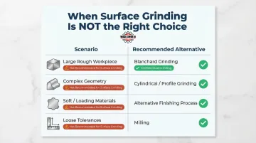
The decision should be based on the drawing, material, stock allowance, production volume, available machinery, inspection requirements, and total process economics.
Explore Specific Surface Grinder Models
If you're ready to explore specific models, T.R. Wigglesworth carries surface grinders suited for precision flat work in production environments. The CSG3A1224 is a 12 x 24 surface grinder well matched to shops looking to add or upgrade surface grinding capability with a machine built for tight tolerances and reliable performance.
| Product | Product Details |
|---|---|
| CSG3A1224 - Clausing Manual Precision Surface Grinder, Hydraulic, 12" x 24" Table Size | Explore Product |
Conclusion
Precision surface grinding transforms machined or heat-treated workpieces into dimensionally accurate, flat, and finely finished components. The process is built on the precise interaction of abrasive wheel selection, controlled infeed, stable workholding, and rigorous thermal management. Its value comes from deploying it where tight tolerances and surface quality are required—with the right machine, wheel, and setup for the job.
For manufacturers evaluating new or used surface-grinding equipment, T.R. Wigglesworth Machinery Company brings the perspective of a family machinery business operating since 1935. The company lists surface-grinder categories and equipment associated with brands including KENT, CLAUSING, ACER, and SUPERTEC and works with customers to match available machinery to their production requirements, application, facility, and budget.
Frequently Asked Questions
What is precision surface grinding?
Precision surface grinding uses a rotating abrasive wheel to produce a controlled flat surface, thickness, parallelism, or surface texture. Achievable results depend on the machine, workpiece size and material, wheel specification, dressing, workholding, thermal control, operator or program, and inspection method, so tolerance and finish should be confirmed for the specific application.
How does a surface grinding machine work?
A surface grinder moves an abrasive wheel relative to a workpiece held on a reciprocating or rotary table. Depending on the machine and application, the spindle may be horizontal or vertical, the workholding may be magnetic, vacuum, or mechanical, and grinding fluid may be used for cooling, lubrication, and swarf removal. The machine removes material through controlled wheel and table motion until the specified dimension, geometry, and surface texture are verified.
How accurate is a surface grinding machine?
There is no single accuracy range for all surface grinders. Capability depends on the machine model and condition, workpiece size and material, stock allowance, wheel and dressing system, workholding, thermal environment, process parameters, operator or program, and inspection method. Flatness, parallelism, thickness tolerance, and surface texture should each be evaluated against the machine manufacturer’s specification and a validated process for the proposed work.
What is the difference between precision and Blanchard ground?
A conventional reciprocating surface grinder usually uses a horizontal spindle and moves the workpiece back and forth beneath the wheel. Blanchard-style grinding usually uses a vertical spindle, segmented wheel, and rotating table and produces a characteristic rotary crosshatch pattern.
Rotary grinding is often considered for efficient processing of comparatively large flat workpieces, while reciprocating grinding is often considered when controlled thickness, parallelism, or a finer linear finish is required. Actual accuracy, finish, cycle time, and cost depend on the machine, workpiece, stock allowance, setup, and inspection requirements.
What are three benefits of precision grinding?
When it is properly matched to the application, surface grinding can provide:
- Controlled flatness, parallelism, or final thickness on suitable workpieces
- A repeatable surface texture produced through a validated wheel, dressing, and process strategy
- Removal of available finish stock after heat treatment, helping correct selected distortion when the part has sufficient material and can be supported without unacceptable deformation
The appropriate process should still be selected by comparing grinding with milling, hard turning, lapping, and other available methods against the drawing and production requirements.
How is surface grinding cost calculated?
Cost depends on setup and programming, initial workpiece condition, stock allowance, cycle time, dressing time and consumables, wheel cost and life, workholding, coolant and filtration, inspection, loading and handling, scrap risk, labor, maintenance, and machine utilization.
Material hardness and tighter specifications may increase cost, but their effect depends on the selected wheel, machine capability, removal strategy, lot size, and inspection plan. Conventional abrasives, CBN, diamond, and other wheel systems should be evaluated only where they are compatible with the workpiece material and supported by the wheel and machine manufacturers’ application data.