Introduction
When shops struggle to explain why a large bore came out slightly off-axis, or why their horizontal boring machine underperforms on deep-hole work, the answer usually traces back to a gap in understanding how the machine actually operates. These machines handle some of the most demanding work in manufacturing — turbine casings, gearbox housings, aerospace structural frames — and the global market reflects that demand, valued at $3.34 billion in 2024 and projected to reach $4.45 billion by 2032, growing at a 6.2% CAGR.
Most operators know what these machines do. Fewer understand the internal logic driving them — how axes interact, what quill travel actually controls, and why spindle mechanics determine whether a bore lands within microns or misses the tolerance entirely. That gap leads to selection errors, setup mistakes, and underutilized capacity.
This guide breaks down how a horizontal boring machine works in practice: the mechanical sequence, component interactions, and the decisions that determine micrometer-level precision.
Key Takeaways
- A horizontal boring machine uses a horizontally oriented rotating spindle to enlarge and finish existing holes in large, stationary workpieces with high dimensional accuracy
- It operates through coordinated X, Y, Z, and W (quill) axis movements to position and feed the cutting tool precisely
- CNC systems automate axis sequencing for repeatable results across aerospace, energy, and heavy equipment manufacturing
- Three main machine types suit different workpiece sizes: table, floor, and planer
- Precision reaches micrometer-level tolerances based on machine class and spindle rigidity
What Is a Horizontal Boring Machine?
A horizontal boring machine is a machine tool built around a horizontally oriented spindle, purpose-designed for enlarging, finishing, and locating holes in large workpieces with tight tolerances for diameter, alignment, and concentricity.
The machine's origins date to 1774, when English industrialist John Wilkinson invented a precision boring machine that accurately bored cast iron cylinders for James Watt's steam engines, widely recognized as the first true machine tool.
The Operational Problem It Solves
Standard milling machines can perform basic boring, but they lack the rigidity, reach, and axial control needed when bore alignment must be maintained across multiple faces of a heavy workpiece. Horizontal boring machines are built specifically to manage those positional relationships. The W-axis (quill) allows the spindle to reach deep into isolated areas without extending the full column, reducing vibration and maintaining consistent alignment on deep holes.
What It Is Not
A horizontal boring machine is not simply a milling machine oriented differently, nor is it the same as a horizontal machining center (HMC). It's also entirely different from directional underground boring used in utilities—a common point of confusion. The machine operates exclusively on internal geometries, unlike a lathe which works external surfaces.
| Feature | Horizontal Boring Machine (HBM) | Horizontal Machining Center (HMC) |
|---|---|---|
| Core Function | Large-part boring & heavy machining | Multi-face milling & drilling |
| Spindle Design | Extendable quill spindle (W-axis) | Fixed spindle |
| Workpiece Size | Very large/oversized parts | Medium to large parts |
| Cutting Focus | Rigidity & torque | Efficiency & versatility |
Why It Remains in Use Today
Despite advanced multi-axis machining centers, bore depth, reach, and workpiece weight requirements in industries like energy and heavy equipment often exceed what a standard HMC can handle. HBMs act like a rigid arm, allowing the tool to reach deep into a workpiece without relying on dangerously long tool holders. When those constraints apply, no standard machining center substitutes for a dedicated horizontal boring platform — which is exactly what the rest of this guide breaks down.
How Does a Horizontal Boring Machine Work?
A horizontal boring machine operates through a defined sequence of setup, axis positioning, and cutting—each stage building on the last to produce a finished bore that meets tight dimensional and positional tolerances.
Workpiece Setup and Initiation
The workpiece is mounted on a table (table-type), floor fixture (floor-type), or dedicated pallet, and the machine is referenced to a datum before any cutting begins. Setup involves datum setting, tool selection, and program loading — performed manually or via CNC-assisted routines on modern machines.
Workpiece setup directly determines bore alignment across multiple faces. Fixturing errors introduced here cannot be corrected downstream, regardless of how precisely the cutting sequence runs.
Core Cutting Operation
The operating principle is direct: the spindle rotates, carrying the cutting tool (boring bar with indexable insert), while the workpiece remains stationary. Feed motion is applied either by advancing the quill (W-axis) for in-spindle travel on deep holes, or by moving the column/table along X, Y, and Z axes for positional changes.
The Axis System:
Industrial HBMs operate on a standardized coordinate system defined by ISO 841:
- Z-axis drives the spindle toward the workpiece
- X-axis provides cross-traverse
- Y-axis handles vertical positioning
- W-axis is the quill (in-spindle travel for deep boring)
- B-axis is the rotary table for indexing to new faces
- C-axis is spindle rotation
The quill is especially important for deep boring because it advances the tool without moving the full column, reducing vibration risk. Major OEMs offer W-axis travel ranging from 500 mm to 1,600 mm depending on model and application.
The Overhang Principle:
Bar extension directly affects cutting accuracy. As the boring bar reaches farther from its anchor point, deflection, vibration, and dimensional error all increase. Two factors keep this in check:
- Operator technique: repositioning the workpiece to minimize overhang
- Machine design: spindle stiffness, precision guideways, and integrated damping systems
CNC Control and Regulation
CNC systems regulate the cutting sequence through multi-axis interpolation, programmed offsets that correct for tool wear, and probing routines that allow in-process measurement without removing the part. This enables repeatability across long-running production cycles.
Thermal expansion, vibration, and axis drift are real threats to bore geometry in extended runs. Modern machines counter these with active stabilization and thermal compensation built into the control system — Okuma's Thermo-Friendly Concept, for instance, holds thermal deformation to under 10 µm across full operating shifts.
Key Components That Drive Performance and Precision
Spindle and Quill
Spindle stiffness and torque directly influence bore quality. A rigid spindle reduces chatter and supports tighter positional tolerance, while the quill provides in-feeding travel for deep-hole operations without relocating the column. Spindle diameter is a key spec when comparing machines for heavy-duty vs. precision work.
Major OEM Spindle Diameter Ranges:
- Fermat: 100 mm to 160 mm (3.94" to 6.3")
- PAMA: 130 mm to 260 mm
- TOS Varnsdorf: 130 mm to 160 mm
- UnionChemnitz: 130 mm to 262 mm
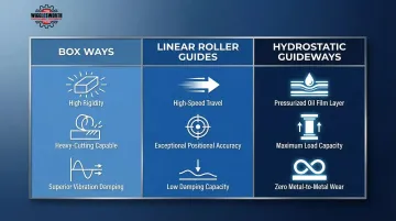
Guideways and Structural Mass
The machine's guideways—whether box, linear roller, or hydrostatic—determine damping behavior and axis accuracy under cutting load. Structural mass is deliberate: it absorbs cutting forces and suppresses vibration that would otherwise translate into bore surface error.
Guideway Trade-Offs:
| Guideway Type | Characteristics |
|---|---|
| Box Ways | High rigidity, heavy cutting, slower speeds with better damping |
| Linear Roller Guides | High-speed machining, precise positioning, less damping |
| Hydrostatic Guideways | Pressurized oil film eliminates wear, exceptional load capacity, superior smoothness |
Hydrostatic guideways are the top choice for ultra-precision and heavy-duty applications. For example, the TOS Varnsdorf WRD 180 H uses 68 closed hydrostatic cells to carry the machine, ensuring precise drilling for workpieces up to 200 tonnes.
Rotary Table
The rotary table (B-axis) enables multi-face boring in a single setup by indexing the workpiece to each face without re-clamping. Indexing accuracy defines bore-to-bore positional relationships—poor indexing undermines precision even when diameter tolerances are met. High-end rotary tables offer indexing accuracies ranging from ±7.5 to ±10 arc seconds.
CNC Control and Tooling Interface
The CNC control ties the system together, coordinating everything from axis movement to tool measurement. Core functions include:
- Axis interpolation for synchronized multi-axis cutting paths
- Tool offset management to maintain dimensional accuracy across operations
- Measurement cycle execution for in-process inspection
- Automatic tool changer integration to reduce non-cutting time
For buyers evaluating machines, T.R. Wigglesworth Machinery Company—an authorized dealer for FEMCO, KENT, and DAH LIH machines since 1935—can help match control specifications and tooling configurations to specific production requirements.
Types of Horizontal Boring Machines
Industrial HBMs are categorized into three primary configurations based on how they handle the workpiece and structural movement:
Table Type — The most common configuration. The workpiece mounts on a moving table, with positioning shared between table movement and spindle feed. This flexible reach makes it well-suited for medium to large components across mixed operations and general machining.
Floor Type — Used for components too large or heavy to reposition. The part sits fixed on a floor plate while the spindle head travels to each feature. Typical applications include turbine casings, large structural frames, and heavy industrial components.
Planer (T-Type) — Designed for complex multi-face operations. A moving column/headstock provides multi-directional access, while the double-length bed supports the table fully throughout its X-axis travel — eliminating overhang deflection. Best suited for workpieces requiring machining from multiple angles in a single setup.
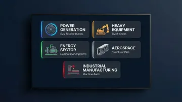
Where Horizontal Boring Machines Are Used
Horizontal boring machines fit primarily in the precision machining phase of manufacturing, after initial material removal by milling or casting. They're used for bearing seat preparation, bore finishing, and multi-face alignment work—operations where bore geometry defines the success of downstream assembly.
Industries and Part Types:
- Power Generation: Gas turbine inner barrels (60" diameter, tolerances of ±0.002")
- Heavy Equipment: Gearbox housings, bearing seats, earthmoving excavator frames
- Energy Sector: Pump, compressor, and valve bodies; wind turbine gearboxes; turbine housings
- Aerospace: Structural frames, large housings, and assembly fixtures with tight positional tolerances
- Industrial Manufacturing: Machine bases and structural components requiring multi-face alignment
HBMs also play a critical role beyond new production. In mining and power generation, worn bores in heavy machinery often get restored rather than replaced—and boring machines make that economically viable.
Remanufacturing and Repair:
Automated bore welding systems interface with line boring machines to weld one bore while machining another, cutting repair times in mining and power generation facilities. Shops perform weld build-up and face machining while holding tolerances of ±0.0005".
The range of applications—from turbine housings to excavator frames to remanufactured compressor bores—reflects how much the machine's capabilities vary by configuration. T.R. Wigglesworth Machinery Company has supplied horizontal boring equipment to precision and heavy manufacturing shops across the U.S. since 1935, and can help match machine specifications to the specific bore geometry and tolerance requirements a job demands.
| Product | Product Details |
|---|---|
| BMC-110R1 | Explore Product |
| BMC-135TN | Explore Product |
| BMC-100HT | Explore Product |
Frequently Asked Questions
How does a horizontal boring machine work?
The machine uses a rotating horizontal spindle to bore into a stationary workpiece, with the tool fed into the part via the quill (W-axis) and positioned via X, Y, and Z axes. CNC systems automate the axis movements for repeatable accuracy.
What is a horizontal boring machine?
A horizontal boring machine is a machine tool built around a horizontally oriented spindle for enlarging, finishing, and precisely locating holes in large workpieces. It differs from standard milling machines and horizontal machining centers through its extendable quill and focus on rigidity over speed.
What is the difference between vertical and horizontal boring machines?
In vertical boring mills the workpiece rotates while the tool is stationary, suited to smaller round parts. In horizontal boring machines the workpiece is stationary and the rotating spindle feeds into it horizontally, making it better for large, heavy, and multi-face components.
What are the different types of horizontal boring machines?
The three main types are table type (most common, moving table), floor type (for very large/heavy parts on a floor fixture), and planer/T-type (moving column for complex multi-face access).
How precise is horizontal boring?
Modern CNC horizontal boring machines hold tolerances in the micrometer range for bore diameter, roundness, and positional accuracy. Precision depends on machine class, spindle stiffness, guideway type, and thermal compensation capability.
How much does a horizontal boring machine cost?
Machine cost varies by size, type, and CNC capability. Used machines average approximately $54,500 in the U.S., while new CNC models typically run $150,000 to $500,000 or more. T.R. Wigglesworth carries both new and used horizontal boring mills and can help match the right machine to your workpiece size and production requirements.