Introduction
A part measuring 84 inches in length simply won't fit on a machine with 50-inch X-axis travel — and turning away that work is an expensive decision that compounds over time. Job shops and heavy manufacturers know the constraint well: parts that exceed the envelope of a standard 40×20 VMC, setup operations that consume hours of spindle time, and constant pressure to boost output without expanding floor space.
Repeatedly repositioning oversized workpieces, manually operating multiple vises, or changing jobs several times per shift can consume substantial spindle and operator time. The actual loss depends on setup frequency, part mix, workholding, inspection requirements, and the number of machines involved.
A traveling-column machine can address these constraints by moving the spindle column along a fixed table or bed. For suitable applications, this architecture provides longer axis travel while reducing the need to move or reposition the workpiece.
But owning one isn't enough. Maximizing productivity requires deliberate strategy in workholding configuration, rapid traverse specification, spindle selection, and setup discipline. Shops that treat a traveling column machine as just a "bigger VMC" leave significant capacity — and revenue — untapped.
Key Takeaways
- Traveling-column machines move the column or spindle assembly along a fixed table, bed, or floor-mounted system, making them suitable for selected long-part, large-part, and multi-fixture applications
- Workholding should be selected according to part geometry, production volume, changeover frequency, required access, and automation plans
- Important specifications include axis travels, table or floor-plate capacity, spindle speed and torque, cutting feed, rapid traverse, tool capacity, control features, and installation requirements
- Potential productivity gains should be confirmed through a cycle-time, setup-time, utilization, handling, and return-on-investment analysis for the shop’s actual workload
What Is a Traveling Column Machine?
Unlike many conventional VMCs, a fixed-table traveling-column machining center moves the spindle column along the machine’s longitudinal axis while the workpiece remains clamped to the table. Available travels vary by model: for example, the KENT KVTC series lists 87-inch and 126-inch X-axis configurations.
Keeping the workpiece stationary can reduce the need to reposition long parts and avoids moving the full workpiece mass through the longitudinal axis. Whether a component can be completed in one setup still depends on tool access, axis travels, workholding, part support, and the operations required.
“Traveling column” describes how a machine axis is arranged rather than limiting the term to only two machine classes. The architecture appears in fixed-table vertical machining centers, large milling machines, and floor-type boring-and-milling systems.
Floor-type machines commonly support workpieces on floor plates, rotary tables, or project-specific foundations. Their allowable workpiece weight is determined by the floor plate, table, foundation, handling equipment, and machine configuration. Some horizontal boring mills include a programmable W-axis boring spindle, while others use different ram, head, or spindle arrangements.
Traveling Column VMC vs. Floor-Type Horizontal Boring Mill
Traveling-column VMCs use a vertical spindle and a fixed table, making them a potential fit for long components, multiple fixtures, and parts primarily requiring vertical milling, drilling, tapping, and related operations. Available rotary-axis options may provide additional part access, depending on the model and configuration.
Floor-type horizontal boring-and-milling machines move the column along a longitudinal bed while the workpiece is supported on floor plates, a rotary table, or another engineered foundation. Their horizontal spindle, ram, available head attachments, and optional boring-spindle travel make them suitable for large components requiring horizontal access or deep boring.
The correct choice depends on part geometry, workpiece mass, required tool approach, bore depth, axis travels, rotary-table requirements, material-removal demands, foundation design, and handling method. Both machine classes may perform milling, drilling, boring, tapping, and facing when appropriately configured.
Core Design Advantages Over Standard Machines
Three potential design advantages distinguish fixed-table traveling-column machines:
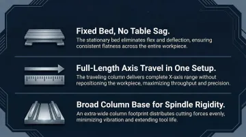
Stationary workpiece support: The workpiece remains on a fixed table, floor plate, or rotary table while the column travels. This avoids moving the full workpiece mass through the longitudinal axis, although the table, floor plate, foundation, and machine still have defined load limits.
Long-part access: Sufficient axis travel can reduce the number of times a long component must be repositioned. Fewer setups may reduce alignment risk and operator time, but one-setup completion depends on tool access, support, axis stroke, and part geometry.
Purpose-designed machine structure: Rigidity depends on the machine casting, guideway arrangement, spindle overhang, ram or head design, thermal management, foundation, and installation. These characteristics should be compared using model-specific specifications and the proposed cutting application.
How Extended Travel Translates to Real Productivity Gains
Extended X-axis travel isn't just about fitting bigger parts—it's a productivity multiplier that transforms how shops structure work, manage setup time, and bid on jobs.
The gains show up across four distinct areas:
- Batch density: A longer table may accommodate additional fixtures or workpieces, subject to table load, fixture spacing, tool access, chip evacuation, collision clearance, and the machining sequence. The achievable unattended runtime must be calculated from the actual cycle time and number of parts loaded.
- Multi-job flexibility: Different fixtures and repeat jobs may be staged on one table when the control, work offsets, probing strategy, tooling, and available work envelope support the arrangement. Switching programs does not remove the need for setup verification, collision checking, and process validation.
- Long-part machining: Additional travel may reduce repositioning and re-indicating for long components. Whether both ends can be completed in one setup depends on part support, tool approach, spindle orientation, axis limits, and required features.
- Expanded quoting envelope: Greater travel can allow a shop to consider work that exceeds its existing machine envelope. The commercial opportunity should still be evaluated against handling, fixturing, cycle time, inspection, utilization, and capital cost.
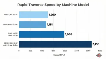
Rapid traverse can reduce non-cutting positioning time when the column must move repeatedly across a long work envelope. However, published rapid rates should be evaluated together with acceleration, deceleration, actual move distances, cutting-feed rates, tool-change time, probing, and the complete machining cycle.
For reference, the KENT KVTC series lists a rapid traverse of 1,260 IPM. Any projected annual time saving should be calculated from the customer’s programs and expected production volume rather than from maximum traverse speed alone.
Workholding and Setup Strategies That Maximize Capacity
Extended table length only delivers value if you can load, unload, and secure parts efficiently. The right workholding strategy transforms a traveling column machine from a single-job platform into a modular production cell.
Four strategies make the biggest difference in daily throughput:
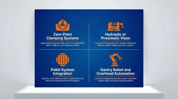
- Zero-point clamping systems: Chucks mounted in a grid let palletized workpieces swap in under one minute. The operator sets up the next pallet offline while the machine is still cutting — eliminating setup downtime and enabling lights-out runs.
- Hydraulic or pneumatic vises: When running eight to twelve vises across a long table, manually cranking each one becomes a fatigue point and a time sink. Hydraulic vises cut clamping time from minutes to seconds per part — especially valuable in high-mix environments where setups change frequently.
- Pallet system integration: Essential for floor-type HBMs handling workpieces exceeding 20,000 pounds. Automated pallet changers stage a new part on one pallet while the machine cuts on another — the same approach DMG MORI applies in its standardized pallet changing systems for precision boring.
- Gantry robot and overhead automation: Gantry-style loading transforms smaller-part batch runs on a traveling column VMC into continuous production. Parts load and unload without interrupting the machining cycle, giving shops running aerospace brackets or medical device components genuine 24-hour utilization.
Workpiece support, clamping force, boring-bar overhang, spindle and machine condition, tooling, cutting parameters, thermal stability, and inspection all affect bore geometry. Required concentricity, roundness, and positional tolerances should therefore be validated through a complete process-capability review rather than attributed to workholding or spindle power alone.
Key Specifications to Prioritize When Selecting or Operating a Traveling Column Machine
Rapid Traverse Speed and X-Axis Travel
Rapid traverse is important when a machine repeatedly positions across a long axis, but there is no universal rate that defines an acceptable traveling-column machine. Acceleration, cutting feed, actual move distance, tool-change time, and complete cycle time are equally important.
The KENT KVTC traveling-column series lists:
- X-axis travel: 87 inches or 126 inches
- Rapid traverse: 1,260 IPM
- Cutting feed: 472 IPM
- Table capacity: 4,408 pounds or 5,511 pounds, depending on model
Axis travel should be selected from the complete part-and-fixture envelope, required approach clearance, future workload, table capacity, floor-space constraints, and expected return on the additional travel.
Spindle Performance: Speed, Power, and Thermal Stability
Spindle specification must match the application. Requirements differ significantly by work type:
- Mold, die, and aerospace work: Evaluate the spindle speed and torque curve, continuous and peak power, tool interface, coolant requirements, thermal management, and intended cutting tools against the material and required operations
- Heavy-duty boring: Evaluate low-speed torque, spindle or quill diameter, ram and spindle travel, overhang, head configuration, tool connection, and chip-removal requirements
- Floor-type HBMs: Spindle diameter, ram travel, W-axis travel, guideway construction, head options, and available tables vary substantially by machine and should be selected from the required bore depth, workpiece geometry, material-removal rate, and accuracy target
Thermal-management equipment may be standard or optional depending on the machine model. On the KENT KVTC series, a spindle chiller is listed as standard equipment, while through-spindle coolant is listed as an available accessory.
T.R. Wigglesworth Machinery Company has been a family machinery business since 1935 and lists KENT among the brands in its machinery catalog. Buyers should confirm current machine availability, configuration, delivery responsibilities, installation scope, training, warranty, and support terms with Wigglesworth for the specific project.
Tool Magazine Capacity and Memory
Tool-magazine capacity should be based on the verified tool list for the intended parts, including common tools, dedicated tools, sister tools, redundant tools for unattended production, probing equipment, and reserve capacity. The number required cannot be determined solely from the number of jobs mounted on the table.
The KENT KVTC series lists 24-, 32-, and 40-tool magazine configurations. A tooling review should confirm whether the selected magazine can support the proposed programs without avoidable manual intervention.
Controller capability is equally important for high-production work. Controller capabilities must be verified for the exact machine, CNC version, software package, sensors, and installed options. Relevant functions may include:
- Workpiece probing: Measures selected features and may update work offsets when the required probe, cycles, and software are installed
- Tool measurement and compensation: Measures tool length or diameter and applies programmed compensation within configured limits
- Load monitoring or adaptive functions: Monitors selected machining conditions and may modify or stop the process according to the available control features
These functions can reduce manual intervention when correctly integrated, but they do not replace validated programs, stable workholding, capable tooling, inspection, or process control.
Industry Applications: Where Traveling Column Machines Deliver the Greatest Advantage
Aerospace and Defense
Aerospace and defense manufacturers may use traveling-column machines for long structural components, fixtures, housings, and multiple-part setups. Multi-face machining depends on the spindle head, rotary-axis configuration, fixture design, and available tool access; required accuracy must be validated against the machine specification and the complete manufacturing process.
Heavy Equipment, Oil and Gas, and Energy
Heavy-equipment, oil-and-gas, and energy applications may involve pump housings, valve bodies, gearbox components, fabrications, and other large workpieces requiring horizontal access. FERMAT’s WRF Heavy floor-type series, which Wigglesworth represents as part of its boring-mill offering, can be configured with floor plates or rotary tables rated for workpieces up to 100 metric tons.
The required machine, foundation, loading system, crane or forklift capacity, table arrangement, and thermal-management strategy must be engineered for the actual workpiece and facility.
Mold and Die Shops and General Job Shops
Traveling-column VMCs may suit mold-and-die shops and general job shops that machine long components, mold bases, fixtures, or multiple smaller parts. Their economic fit should be established by comparing the part envelope, table capacity, required operations, setup reduction, expected utilization, tooling, facility cost, and alternative machine architectures.
T.R. Wigglesworth evaluates machinery projects using the required machining envelope, table capacity, and materials rather than assuming that one machine class will provide the best return for every mixed-work shop.
| Product | Product Details |
|---|---|
| BMC-135TN | Explore Product |
| BMC-135TNL | Explore Product |
| BMC-110R1 | Explore Product |
Frequently Asked Questions
What is the boring process in a milling machine?
Boring on a milling machine uses a boring head or boring bar mounted in the spindle to enlarge and finish a pre-existing hole to precise diameter, roundness, and concentricity. Unlike drilling, which creates a new hole from solid material, boring refines an existing hole to tight tolerances.
What is a traveling column machine and how does it differ from a standard VMC?
In a fixed-table traveling-column machining center, the spindle column moves along the longitudinal axis while the workpiece remains clamped to the table. This arrangement can provide longer travel and avoid moving the workpiece through that axis, but allowable workpiece weight and machine accuracy remain model-specific.
How does X-axis travel length affect productivity in traveling column machines?
Longer X-axis travel may allow a machine to accommodate longer parts or additional fixtures and can reduce repositioning for suitable work. The productivity effect depends on tool access, table capacity, workholding, cycle time, loading, probing, tool changes, and whether the additional travel removes an actual process constraint.
What workholding method best maximizes capacity on a traveling column machine?
No single workholding method is best for every application. Selection may include direct clamping, dedicated fixtures, manual or powered vises, zero-point systems, pallets, floor plates, or rotary tables based on part geometry, weight, cutting forces, required access, volume, changeover frequency, automation, and tolerance requirements.
When is a traveling column machine the right choice over a gantry machine or horizontal boring mill?
A traveling-column machine may be appropriate when the required part-and-fixture envelope, stationary-workpiece arrangement, tool approach, spindle orientation, table capacity, and production mix match that architecture. A gantry machine or horizontal boring mill may be more appropriate when the work requires different multi-axis access, heavier capacity, deeper horizontal boring, larger vertical clearance, or another foundation and handling arrangement. T.R. Wigglesworth recommends beginning the selection process with the machining envelope, desired table capacity, workpiece material, required operations, and project objectives so the machine configuration is matched to the application rather than a single size threshold.