Introduction
Spindle speed range governs whether a boring mill can handle a given workpiece diameter, material, and operation type — not just how efficiently it performs, but whether it can perform at all. Many manufacturers struggle with chronic tool wear, poor bore accuracy, and premature spindle failures, often unaware that the root cause is operating outside their machine's effective speed-torque envelope.
According to tooling industry standards, most misapplication traces back to a single source: the relationship between cutting speed, bore diameter, and required RPM is poorly mapped during machine selection and process planning.
Understanding the full operating range of a boring mill spindle — including low-speed torque limits, high-speed boundaries, and the tradeoffs between them — is essential for correct machine specification and reliable long-term operation. This guide breaks down how spindle speed range is defined, what shapes it in practice, and where misapplication leads machines and operators into trouble.
Key Takeaways
- Boring mill spindle speed spans a low-speed, high-torque minimum to a high-speed, lower-torque maximum — the correct RPM depends on workpiece diameter, material, and operation type
- Most industrial boring mills operate in low gear for large-diameter heavy roughing, shifting to higher ranges for semi-finishing and fine boring
- Surface footage, bore diameter, and the speed-torque curve together determine the correct operating zone — RPM alone is not enough
- Operating outside recommended ranges causes accelerated tool wear, poor surface finish, bore inaccuracy, and spindle damage
- Spindle speed range is a design parameter validated through power-speed curves — nameplate specs tell only part of the story
What Spindle Speed Range Means in a Boring Mill
Spindle speed is the rotational rate (RPM) of the spindle — driving the boring tool in horizontal boring mills, or rotating the workpiece on a faceplate in vertical turret lathes and vertical boring mills. "Spindle speed range" refers to the entire spectrum from minimum sustainable RPM under load to maximum rated RPM, not a single fixed value.
The fundamental relationship linking spindle speed to cutting speed and bore diameter is:
RPM = (Cutting Speed × 12) / (π × Diameter) (imperial units)
Because boring involves large diameters, even moderate surface footage demands very low RPM. Boring a 20-inch diameter bore in carbon steel at 200 SFM, for example, requires only 38 RPM — making boring mills inherently low-speed, high-torque machines compared to milling or turning centers.
Spindle speed range is built into the machine's drive system through gearbox stages, motor winding configurations, or variable-frequency drives. This range determines what surface footage is achievable across different bore diameters — and by extension, which materials and operation types are feasible on that machine.
Gear Ranges and Their Purpose
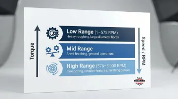
Industrial boring mills typically use multiple gear ranges — low, medium, and high:
- Low range: Maximizes torque for heavy roughing cuts on large-diameter bores
- Mid range: Balances torque and speed for general semi-finishing operations
- High range: Prioritizes speed for fine boring of smaller features and finishing passes
Range selection is controlled via M-codes in CNC boring mills. Where ranges overlap in RPM, operators choose based on torque demand — running a higher gear at lower RPM delivers less torque than dropping to the next range down at the same speed.
Representative Spindle Speed Ranges
| Machine Type | Model Example | Minimum RPM | Maximum RPM | Spindle Diameter |
|---|---|---|---|---|
| Horizontal Boring Mill | FEMCO BMC-135TN | 1 | 3,000 | 135 mm |
| Horizontal Boring Mill | TOS Varnsdorf WRD 170 | 10 | 2,200 | 170 mm |
| Horizontal Boring Mill | Giddings & Lewis FT 3500 | Not specified | 4,000 | 130 mm |
| Vertical Turret Lathe | Webster & Bennett Millennium | 1 | 400 | N/A (Table) |
The FEMCO BMC-135TN illustrates typical gear range architecture: low range covers 1–575 RPM, while high range spans 576–3,000 RPM, ensuring adequate torque delivery across the full operating spectrum.
Factors That Shape Required Spindle Speed in Boring Operations
Material Hardness and Machinability
Harder materials require lower surface footage, which translates directly to lower RPM for any given diameter. The table below shows recommended surface footage ranges and calculated RPM for a 20-inch bore:
| Material | ISO Group | Recommended SFM | Required RPM (20" Bore) |
|---|---|---|---|
| Cast Iron | ISO K | 130-260 | 25-50 |
| Carbon Steel | ISO P | 200-390 | 38-74 |
| Stainless Steel | ISO M | 200-300 | 38-57 |
| Inconel/Nickel Alloys | ISO S | 70-130 | 13-25 |
| Aluminum | ISO N | 260-490 | 50-94 |
| Bronze/Copper Alloys | ISO N | 80-380 | 15-73 |
SFM data sourced from Iscar tooling standards.
For high-temperature alloys like Inconel, boring a 20-inch diameter requires spindle speeds as low as 13 RPM. That falls well below the minimum capability of most standard machining centers, making multi-stage gearbox drive systems a necessity rather than an option.
Bore Diameter and Workpiece Size
As diameter increases, required RPM for the same surface footage decreases sharply. Consider boring carbon steel at 200 SFM (a typical finishing speed):
- 10-inch bore: Requires 76 RPM
- 20-inch bore: Requires 38 RPM
- 40-inch bore: Requires 19 RPM
- 60-inch bore: Requires 13 RPM
This inverse relationship means that large-diameter workpieces common in boring mill applications demand machines capable of maintaining full torque at extremely low speeds.
Bar geometry introduces another constraint on top of diameter — one that can push required speeds even lower than the material alone would suggest.
Boring Bar Length and Overhang
Boring bar length-to-diameter (L:D) ratio directly limits maximum usable speed:
- Solid steel bars: 4:1 maximum (general purpose)
- Heavy metal tungsten bars: 6:1 maximum (better damping)
- Solid carbide bars: 6:1 to 8:1 (high stiffness)
- Steel damped bars: 10:1 maximum (tuned vibration suppression)
- Carbide-reinforced damped bars: 14:1 maximum (deep-reach applications exceeding 10:1 L:D)
Longer bars are more susceptible to deflection and chatter. Operators must reduce spindle speed below the theoretical optimum to maintain stability, even if the material and diameter would otherwise permit higher RPM.
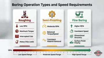
Operation Type: Roughing vs. Semi-Finishing vs. Fine Boring
- Roughing: Demands low speed and high torque to manage interrupted cuts and heavy chip loads
- Semi-finishing: Requires moderate speed for balanced material removal and surface quality
- Fine boring: Requires consistent speed for dimensional accuracy and surface finish
A boring mill handling all three operation types — on the same workpiece, in the same setup — needs a spindle speed range wide enough to shift from high-torque roughing passes at under 20 RPM to fine boring at 80+ RPM without losing accuracy or requiring a machine change.
The Operating Speed Range: Zones, Limits, and Safe Margins
Three interacting constraints govern boring mill spindle speed range: the mechanical design limits of the drive system, the power-torque curve from the spindle motor, and the application requirements of the workpiece. Together, these define distinct operating zones within the published range.
Nominal Operating Range
Industrial boring mills typically span from single-digit RPM at the low end (for very large diameter VTL work) to several hundred or low thousands of RPM at the high end (for precision boring of smaller bores). For example:
- Horizontal table-type boring mills: Typically 1-3,000 RPM across gear ranges
- Large VTL boring mills: Typically 1-400 RPM for table rotation
The published range assumes stable cutting conditions with rated load, ambient temperature, calibrated tooling, and proper workpiece clamping. Interrupted cuts, out-of-balance workpieces, or worn tooling can narrow the practical range significantly.
Upper Speed Limits
Three factors cap the upper speed limit:
- Bearing rated speed: Thermal limits of bearing lubrication films
- Centrifugal force: Acting on the spindle, faceplate, and workpiece
- Dynamic balance: Of the workpiece fixture
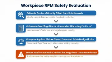
Operating near maximum rated RPM with large or unbalanced workpieces is especially hazardous in boring mills. According to ISO 1940-1 balancing standards, unbalance creates centrifugal force that increases with the square of RPM (F = U × ω²), meaning small imbalances at high speeds generate enormous destructive forces.
Lower Speed Limits
The drive system's ability to maintain torque and stable rotation under load sets the minimum sustainable spindle speed. Below this threshold:
- The spindle may exhibit cogging (uneven rotation)
- Motor vibration increases
- Constant Surface Speed (CSS) operations fail to hold target surface footage
Attempting to run large cutters at low RPM by simply turning down a VFD without mechanical gear reduction results in proportional horsepower loss. For example, running at 1/4 rated RPM yields only 1/4 rated horsepower, causing torque stalls during heavy cuts.
Safe Operating Margin
Manufacturers publish maximum speeds that include built-in derating margins. Operators should target the mid-range of each gear zone rather than boundaries, particularly in heavy-duty boring.
Running chronically close to the upper boundary accelerates:
- Bearing fatigue accumulation
- Thermal overload of the drive system
- Reduced spindle accuracy over time
Factors That Govern Required Spindle Speed Range in Your Application
Spindle speed range for a boring mill application comes from the intersection of material, geometry, and operation type — no single table covers it. Mismatching machine range to application produces predictable results: tool chatter, accelerated insert wear, and tolerances that drift at the worst point in the cut.
Tooling Geometry and Insert Selection
The boring insert geometry, nose radius, and coating affect minimum and maximum speeds:
- Sharp, PVD-coated inserts: Run near the top of the speed range for light finishing passes
- Heavy roughing inserts: Require lower speeds and higher torque to prevent edge fracture
- Larger nose radii: Generate higher radial forces, effectively lowering the practical speed ceiling on flexible setups
PVD-coated grades typically have sharper edge lines than CVD-coated grades, resulting in lower cutting forces and reduced torque requirements — allowing higher speeds with equivalent power.
Workpiece Characteristics Beyond Material
Weight distribution, balance, fixture compliance, and part rigidity all influence maximum safe spindle speed:
- Unbalanced castings on large VTL faceplates may require operators to cap speed well below the machine's rated maximum
- Asymmetrical workpieces create dynamic loads that increase with the square of RPM
- Fixture compliance limits the radial cutting forces the setup can withstand
Evaluate risk by:
- Estimating the workpiece's center of gravity offset from the rotation axis
- Calculating centrifugal force at intended RPM
- Comparing against fixture clamp force and table design limits
- Derating maximum RPM by 30-50% for irregular or unbalanced parts
Constant Surface Speed (CSS) Mode Interaction
In boring mills with CSS capability (G96), the CNC automatically adjusts RPM as the boring tool moves to different diameters, recalculating to maintain target surface footage.
CSS mode drives the spindle toward its maximum RPM as the tool approaches smaller diameters near the bore center. Always program a G50 maximum RPM clamp to prevent:
- Workpiece imbalance generating excessive centrifugal force
- Chuck jaw centrifugal unloading (where rotational force relieves clamping pressure)
- Catastrophic fixture failure or workpiece ejection
Without a G50 limit active, CSS will chase the programmed surface speed until mechanical limits — not programmed ones — stop the spindle.
How Spindle Speed Range Is Specified and Validated
Specification and Documentation
Spindle speed range data is found in:
- Manufacturer datasheets: Published nominal ranges
- Machine tool standards: ISO 230-series for testing and verification
- Engineering drawings: Detailed drive system architecture
Distinguish between:
- Rated (continuous) speed: Sustainable indefinitely under full load
- Peak (intermittent) speed: Allowable for short duration (e.g., 30-minute rating)
Beyond rated vs. peak distinctions, the constant-power bandwidth within the speed range determines practical versatility more than peak RPM alone. Above the base speed, spindle motors enter the field-weakening range where available torque decreases inversely with speed. A wide constant-power band means the machine maintains adequate cutting force across a broader RPM spectrum.
Measurement and Field Verification
Operators verify spindle speed using:
- CNC spindle speed readout: Commanded speed from controller
- Spindle encoder feedback: Actual measured speed
- Handheld tachometer: For older machines or independent verification
The speed displayed on the control may not match actual spindle speed — especially in older gear-head machines or after drive system wear. Newall Electronics DRO systems can provide accurate real-time spindle speed monitoring on retrofitted machines by reading encoder signals directly.
T.R. Wigglesworth Machinery Company has been sourcing and evaluating boring mills since 1935, including the Webster & Bennett VTL line. Their technical team can confirm whether a machine's documented speed range holds up against your specific application requirements before you commit to a purchase.
What Happens When You Operate Outside the Optimal Speed Range
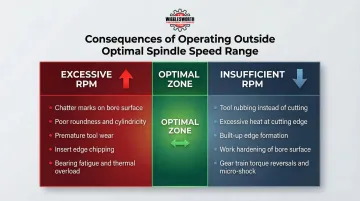
At Excessive RPM: Torque Starvation and Chatter
Operating at excessive RPM causes available torque to drop below what the cut demands. The spindle decelerates under load, producing:
- Chatter marks on the bore surface
- Poor roundness and cylindricity
- Premature tool wear from inconsistent chip formation
- Insert edge chipping from thermal stress and impact loading
The sequence is direct: inadequate torque at speed causes spindle deceleration under load, which creates variable chip loads — and variable chip loads produce vibration and poor surface finish.
At Insufficient RPM: Rubbing and Heat Generation
Operating at insufficient RPM means the tool rubs rather than cuts cleanly, especially in steels and stainless alloys. This generates:
- Excessive heat at the cutting edge
- Built-up edge formation
- Work hardening of the bore surface
- Rapid tool failure
Accelerated Wear and Failure Modes
Sustained operation near the upper speed boundary increases bearing contact stress and thermal load, leading to premature bearing failure.
Chronic overloading degrades the lubricant film between bearing rolling elements and races. Once that film breaks down, wear accelerates — micro-welding and pitting follow, ending in spindle seizure.
Operating at the lower boundary with heavy cuts induces torque reversals and micro-shock loads on the gear train. Heavy cutting loads at low RPMs can crack gear teeth, shear shafts, and rapidly accelerate wear if torque exceeds mechanical limits.
Common Misinterpretations
Three errors show up repeatedly in the field:
- Nameplate RPM treated as a target, not a limit. The maximum rating defines the ceiling. Ignoring the diameter-SFM relationship when setting speed leads to systematic over-speeding on every job.
- Milling center speeds carried over to boring mills. These machines operate at fundamentally different torque levels and workpiece scales. Speeds that work on a machining center will underperform — or damage tooling — on a boring mill.
- Wide speed range mistaken for broad versatility. A published range of 1–4,000 RPM looks capable on paper, but if the constant-power band is narrow or the torque curve drops sharply at low speeds, the machine won't support both ends of that range in practice. Check the speed-torque curve, not just peak RPM.
| Product | Product Details |
|---|---|
| BMC-110R1 | Explore Product |
| BMC-135TN | Explore Product |
| BMC-100HT | Explore Product |
Conclusion
Spindle speed range is a governing machine parameter that defines which materials, diameters, and operations a boring mill can perform reliably. Operating outside that envelope — or choosing a machine without fully understanding it — leads to systematic underperformance, not just occasional quality issues.
That underperformance compounds over time. As workpiece requirements shift, periodically reassessing whether your machine's speed range still fits the application is sound practice. Published specifications tell you the boundaries — real cutting conditions, material properties, and process stability determine whether you're working within them productively.
Frequently Asked Questions
What is spindle speed in milling?
Spindle speed is the rotational rate (RPM) of the spindle holding the cutting tool. In boring mills specifically, it governs surface footage at the workpiece diameter and is typically much lower than in milling applications due to the larger diameters involved.
Why is spindle speed important?
Spindle speed directly determines cutting efficiency, surface finish quality, tool life, and material removal rate. Incorrect speeds in boring operations cause poor bore accuracy, premature tool wear, and spindle damage.
What is the minimum speed for a spindle?
The drive system's ability to maintain stable torque under load determines the minimum sustainable spindle speed. In boring mills machining very large-diameter workpieces, that minimum can reach single-digit RPM to hold correct surface footage without overloading the drive.
Why is spindle speed reduced when machining harder materials?
Harder materials require lower surface footage to prevent excessive heat generation, rapid tool wear, and edge failure. Since RPM and surface footage are directly proportional at any given diameter, a lower SFM requirement means a lower operating RPM for the same workpiece size.
What is the purpose of a spindle in CNC?
The spindle is the rotating axis that transmits cutting force and motion. Depending on the machine type, it rotates the tool (boring mills, machining centers) or the workpiece (VTLs). Speed range, torque output, and stiffness together determine the machine's ability to perform a given operation accurately and repeatably.
How do I know if my boring mill has the right spindle speed range for my application?
Calculate the required RPM from your target surface footage and workpiece diameter across the full operation range, from roughing through finishing. Then compare those values against the machine's speed-torque curve, not just the nameplate RPM, to confirm adequate power is available throughout.