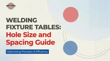
Introduction
Welding fixture table holes define the entire fixturing system — which clamps, pins, and stops will work, how precisely workpieces can be positioned, and how repeatable setups will be across projects. Get the hole specs wrong and every accessory purchase becomes a compatibility problem.
Yet most buyers focus on table size and material while overlooking hole specifications. Without compatible accessories, a fixture table is just a heavy steel slab with a grid pattern on it.
This guide breaks down what D16, D28, grid spacing, and pattern layouts actually mean in practice. You'll learn which systems are compatible, how hole tolerance affects repeatability, and how to choose the configuration that matches your application instead of forcing workarounds later.
Key Takeaways
- Fixture table holes form a standardized positioning system — hole diameter controls accessory fit, grid spacing controls positioning flexibility
- D16 (16mm diameter, 50mm centers) and D28 (28mm diameter, 100mm or diagonal 50mm centers) use different accessories and cannot share tooling
- Tighter spacing (50mm centers or diagonal layouts) delivers more clamping positions; wider spacing (100mm) simplifies setup for general fabrication
- Tight hole tolerance (±0.05mm) is what makes repeatable positioning possible — loose tolerances undermine accuracy regardless of pattern
- Choose your system based on load requirements, workpiece size, and which fixture accessories you plan to use
What Hole Size and Spacing Actually Do in a Welding Fixture Table
The holes in a welding fixture table are precision-machined locating features that accept standardized pins, clamps, and fixture bodies. They transform a flat plate into a modular, reconfigurable positioning system.
Two separate parameters define this system:
- Hole diameter controls which tooling physically fits — a 16mm pin won't seat in a 28mm hole without an adapter, and adapters introduce play that undermines precision
- Hole spacing (center distance) sets positioning resolution — how finely you can shift fixture location across the table surface
Together, these two parameters define the limits of your entire fixturing workflow. Get them wrong for your application and no amount of quality tooling will compensate.
How well these parameters perform in practice depends on three interacting factors.
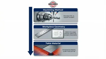
Factors That Affect Hole System Performance in Real-World Use
- Machining method: CNC-bored holes deliver repeatable, precise positioning. Manually drilled holes introduce variation that accumulates across multiple fixtures — undermining the modular system entirely.
- Workpiece geometry: Large structural frames tolerate 100mm center spacing. Small or complex assemblies need 50mm centers or finer to give you meaningful incremental adjustment.
- Table material: Cast iron (such as GG25 / EN-GJL-250) holds dimensional stability better than mild steel under heat cycling. It resists thermal expansion, so hole geometry stays consistent after repeated welding sessions rather than drifting over time.
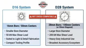
The Standard Systems: D16 vs. D28 Explained
D16 and D28 are complete, incompatible tooling ecosystems — not just hole sizes. Pins, clamps, stops, and squares are manufactured to fit one system or the other, and mixing requires adapters that reduce precision. That incompatibility matters because your hole system choice determines which tooling library you can build over time.
D16 System (16mm Diameter, 50mm Centers)
The D16 configuration uses 16mm diameter holes on a 50mm center grid. It's a compact, fine-resolution system suited to smaller workpieces, precision applications, and situations where clamping positions must be closely spaced.
Limitations:
- Smaller hole diameter restricts load rating of individual fixtures
- Physical size of compatible tooling is smaller
- Best for lighter-duty or detail work, not heavy structural fabrication
D28 System (28mm Diameter, 100mm or Diagonal 50mm Centers)
The D28 configuration uses 28mm diameter holes, available in 100mm standard spacing or diagonal 50mm-center layouts. This is the industry-standard heavy-duty system with the broadest accessory ecosystem and widest compatibility across commercial fixturing suppliers.
Why D28 dominates industrial use:
- Larger 28mm bore accommodates heavier-duty pins and clamps with higher clamping forces
- D28 components handle substantially higher loads — for example, Demmeler's D28 PC bolt has a max shear force of 200 kN versus 50 kN for D16
- Most professional-grade fixture accessory kits — clamp sets, locating squares, V-blocks, stops — are designed and stocked for D28
- Lower-risk long-term investment for shops expanding their tooling library
Shops sourcing welding fixture tables through dealers like T.R. Wigglesworth Machinery Company should confirm which hole system a table uses before purchasing — accessory availability and long-term tooling investment hinge on that single specification.
Hole Spacing and Grid Patterns: 50mm Centers, 100mm Centers, and Diagonal Layouts
Hole spacing defines positional resolution: the minimum distance by which a fixture can be relocated. Finer spacing means more incremental control, which directly reduces setup time for non-standard geometries.
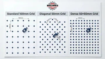
Standard 100mm Grid
The 100mm center-to-center layout is a simple orthogonal grid:
- Reliable all-rounder for general fabrication
- Wide fixture compatibility
- Easy to reference mentally when setting up
- Well suited to larger workpieces where sub-100mm precision is not required
When a workpiece demands a clamping position between hole centers, you must adapt via standoffs or shims — adding setup steps that tighter spacing eliminates. That limitation is precisely what the diagonal layout addresses.
Diagonal 50mm Grid
A diagonal (offset) grid places holes at 50mm center distances but at 45° angles to the orthogonal (right-angle) axes. This expands accessible clamping positions and allows fixture placement at angles not possible on a straight grid.
Irregular or angled workpieces that force awkward setups on a standard grid often fixture cleanly on a diagonal layout, cutting setup time for complex assemblies without additional adapter blocks.
Dense 50×50mm Orthogonal Grid
The 50×50mm straight grid is the highest-resolution standard layout, with hole centers at 50mm in both axes. It provides maximum in-line clamping positions and tightest incremental adjustment.
Suited to:
- Precision components
- Small assemblies
- Applications where dimensional accuracy is critical
A denser hole pattern does not inherently weaken the table. Cast iron tables with properly proportioned ligaments maintain rated load capacity at 50mm spacing — wall thickness between holes is the key engineering variable.
Tolerance, Precision, and Why the Numbers Matter
Hole position tolerance — typically ±0.05mm on center distance and ±0.05mm on diameter — is what makes fixture repeatability possible. This specification separates a precision welding table from a plate with drilled holes.
How Tolerance Error Accumulates
In multi-fixture setups, positional error compounds. If each hole carries ±0.05mm error, a configuration using four or five fixture points stacks that error — making tight individual hole tolerance essential for assemblies with close dimensional requirements.
Hole tolerance alone doesn't tell the whole story. A table with tight hole tolerances but poor surface flatness still produces dimensional errors. Professional-grade welding tables are typically flat to within 0.1–0.2mm per meter, and both specs must be evaluated together.
Why Cast Iron Is the Standard Material
Material selection is the third variable that determines whether these tolerances hold up over time. Cast iron — such as GG25 / EN-GJL-250 — maintains hole geometry through years of production use for four key reasons:
- Resists thermal expansion from weld heat cycles
- Naturally repels weld spatter adhesion
- Does not burr or deform at hole edges
- Maintains dimensional stability under repeated clamping loads
Choosing the Right Hole System for Your Application
Two decisions drive the right system selection: hole diameter and grid spacing.
Start with hole diameter based on your duty level:
- D16 (16mm): Light fabrication, prototype work, and detail assemblies
- D28 (28mm): Heavy structural work and high-volume production environments
Then select grid spacing based on workpiece complexity:
- 100mm grid: Large, straightforward parts where fewer reference points suffice
- 50mm or diagonal grid: Small, complex, or angled assemblies that need tighter fixture positioning
Whichever system you choose, every accessory — clamps, pins, stops, squares — must match that hole standard. Before committing, check the depth of the accessories catalog available for each system in your region.
| System | Ideal For | Workpiece Type |
|---|---|---|
| D16 (16mm) | Light to medium-duty fabrication, precision parts, prototypes | Lightweight materials, smaller components |
| D28 (28mm) | Heavy-duty industrial applications, large-scale production, structural steel | Large, heavy materials (beams, pipes), heavy frames |
One pitfall worth calling out: choosing a cheaper table with inferior hole tolerances to save upfront cost. If hole positions are out of spec, the table produces inconsistent setups regardless of how precise the fixtures attached to it are.
Common Misconceptions About Welding Table Holes
Three myths come up repeatedly when fabricators are choosing between hole patterns and tooling systems. Here's where the logic breaks down.
"More holes mean a weaker table"
Properly engineered tables account for material removal in their structural design. Hole density is not the primary driver of load capacity — wall section thickness, material grade, and rib geometry are. According to GPPH's engineering documentation, dense ribbing and increased plate thickness maintain structural integrity even at 50mm spacing.
"Hole size and spacing are interchangeable between systems"
This is one of the most expensive misconceptions in practice. D16 and D28 tooling is not cross-compatible. Buying a D16 table and later trying to run D28 clamps — or vice versa — forces you into adapters that introduce mechanical play and compromise the precision you paid for.
"Denser hole patterns always produce better results"
For large-scale structural fabrication, a 100mm standard grid is often faster to set up and easier to reference mentally than a 50mm grid. Fewer positions to evaluate means faster fixturing — and in a production environment, that speed adds up. Finer pitch works best for tight-tolerance assemblies, not every job on the floor.
| Product | Product Details |
|---|---|
| 4'x8' Welding Table | Explore Product |
| 3'x8' Welding Table | Explore Product |
| 4'x4' Welding Table | Explore Product |
Frequently Asked Questions
What are the holes for on a welding table?
The holes accept standardized pins, clamps, stops, and fixture bodies — allowing workpieces to be precisely located and clamped in repeatable positions without tacking or building custom jigs for each job.
What is the difference between D16 and D28 welding table?
D16 refers to 16mm diameter holes (typically on 50mm centers) suited to lighter or detail work. D28 refers to 28mm diameter holes (on 100mm or diagonal 50mm centers) used for heavy-duty industrial fabrication. They are incompatible systems with separate accessory ecosystems.
What is a good size for a welding table?
Common professional sizes range from 1000×1200mm to 2000×3000mm. Choose a surface that exceeds your largest typical workpiece, balanced against available shop floor space and budget.
Is 3/8 thick enough for a welding table?
3/8 inch (approximately 10mm) plate is undersized for most professional use — it can flex under load and warp from heat. Professional-grade cast iron fixture tables typically run 100–200mm thick (including ribbing), while steel tops intended for heavy fixturing are generally 20mm or more.
How flat should a welding table be?
Professional welding fixture tables are typically flat to within 0.1–0.2mm per meter. For high-precision work, flatness should be confirmed against the manufacturer's specification and periodically re-checked, as heat cycling and heavy use can cause gradual distortion.
Should you ground a welding table?
Yes. Stray current traveling through fixture pins and clamps damages precision surfaces and creates erratic arc behavior. Many professional tables include a dedicated earth connector point rated for high current — for example, Siegmund's ground connection handles up to 500 Amperes.